FMT Setup N9XR April 15, 2009
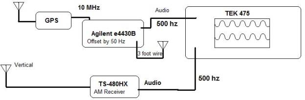
Since the receiver section of the Kenwood is greater than a few Hz, I arbitrarily selected 500 Hz as a frequency offset to beat the FMT signal with the signal generator signal. The RF output of the signal generator is connected to a small wire for a low level signal injection to my receiver antenna. The signal generator also has an audio output. This is inputted and triggered by the TEK 475 scope.
The TS-480 is set to receive AM. I set the RF output to a level where I receive maximum heterodyne. That audio is inputted into the scope. The RF output can be set to 10 milli Hertz increments.
The RF output is adjusted to the 500 Hz so that the signal on the scope stops moving. I did have much trouble with the propagation shifting on 40M, and 80M was not nearly as bad from OK.
A better method here would be to set the frequency as close as possible as soon as possible and measure phase offset with a counter while inputting the data through HPIB into a spreadsheet to calculate the total phase drift and cancelling out the obvious phase shifts from propagation. The data would have to be manipulated, but it could be don