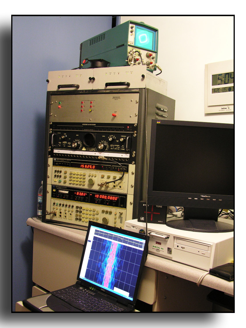
W6OQI FMT Methodology
This is a picture of
the off-air frequency measuring setup used at W6OQI.
The scope on top is used for zero beating.
Under the scope are two HP Z3801A GPS receivers.
Below the GPS receivers is a Spectracom WWVB receiver that has everything
inside disconnected except for the power supply and the five output distribution
amp. The output of one of the GPS
receivers feeds the input of the five output distribution amplifier.
One of the outputs from the distribution amplifier feeds the external
reference input of the HP 3586B selective level meter.
Another output feeds the external reference input of the HP 3336B signal
generator. Below the Spectracom
WWVB receiver is an audio distribution amplifier not related to frequency
measuring. Below the audio
distribution amplifier is a Dovetron RTTY demodulator that also is not related
to frequency measuring. Below the
Dovetron is a video patchbay that is used for patching the output of the GPS
receivers and the HP 3336B signal generator.
When transmitting a FMT the output of the HP 3336B is patched to the
input of a more than 50 year old Johnson Viking I that in turn feeds, via a 6 dB
attenuator, an Icom PW-1 driven to 500 Watts output.
At the bottom of the rack is the HP 3856B selective level meter. Above this is the HP 3336B signal generator.
In the picture the output of the signal generator is patched into the
horizontal input of the oscilloscope via the patch bay.
The
frequency standard is GPS referenced using two, HP Z3801A GPS receivers with a
10 MHz output. Both receivers are
running off a common antenna.
I
learned my methodology from Burt Weiner, K6OQK, and as Burt explains, “For the
FMTs I use a GPS referenced HP-3586B as my receiver. The conversion oscillators
within the HP-3586 are derived from the time base. This means that for an
incoming signal that is exactly on the "tuned-to" frequency of the
receiver, the resultant I.F. will be exactly 15,625.000 Hz. I've added a
pick-off point for the receiver's 15,625 Hz I.F. that I can feed to one side of
an oscilloscope and at the same time to Spectrum Lab that runs on my Laptop
computer. Spectrum Lab has also been calibrated to this laptop. The other side
of the oscilloscope is fed with a GPS referenced HP-3336A precision signal
generator, which coincidentally is the companion generator for the HP-3586
series instruments. The signal generator is then set to 15,625.00 Hz to produce
a 1:1 Lissajou display on the oscilloscope.
Because
of the conversion scheme used in the HP-3586B, the I.F. error is in the opposite
direction of the incoming signal's error. By using this I.F. method I have
totally removed the steps and the need to calibrate around the Product Detector
and its 1850 Hz tone errors.
I start by presetting my receiver’s memories to the FMT’s published frequencies as well as the receiver parameters I want to start with. Since I’ve recently started using the time-averaged results from spectrum Lab for measurements over long paths, I want to get as close to the correct frequency as soon as I can in order to give Spectrum Lab as much time as possible to time-average the signal without my tuning the receiver.
As
soon as I hear the FMT station’s CW Call-Up announcement I immediately begin
to tune the HP-3586B receiver, starting with the 3.1 kHz bandwidth, first in 10
Hz steps and then as I get closer I to the actual frequency I reduce the
frequency steps to 1 Hz and reduce the I.F. bandwidth of the HP-3586B to 400 Hz
and eventually to the 20 Hz bandwidth position, all the time homing in to
produce as close to a 1:1 stationary Lissajou as possible. Using the
oscilloscope and the Lissajou I can usually get within 1 Hz or very close to 1
Hz during the CW Call-Up announcement.
The
reason I personally prefer to use 1 Hz steps is that it is much easier for me to
quickly work with whole numbers than fractional or decimal numbers. Once the
receiver is tuned to the nearest whole cycle (Hz) I can move the HP-3336A’s
frequency in milliHertz steps to make the Lissajou pattern stand still -
something that can rarely be accomplished in a actual FMT over a long path due
to Doppler shift. The receiver’s 15,625.00 Hz I.F. is also monitored using the
waterfall display of Spectrum Lab set for +/- 5 Hz of the 15,625 Hz center
frequency. This allows me to time average the incoming signal's frequency for
the duration of the FMT's key down period.
Here’s
an example: If the HP-3586 receiver ends up tuned to 3,555,654.0 Hz to produce
the closest to a 1:1 stationary display then I know I am within 1 Hz. I can then
move the HP-3336A generator to try and make the Lissajou stand still. If the
HP-3336A ends up being 15,624.33, then I know the error is 0.67 Hz (15,625.00 Hz
-15,624.33 Hz = -0.67 Hz) (corrected to a +0.67 Hz because of the conversion
direction) as received at that moment. If Spectrum Lab and the Lissajou agree
over the three-minute key down period it's a miracle. Depending on the direction
of the error I will either add or subtract that I.F. error to the
"tuned-to" frequency of the HP-3586B. In this example the measured
frequency is 3,555,654.67 Hz.
Note
that with this method, tuning the 3336A does not affect the operation or
accuracy of Spectrum Lab’s time averaging of the frequency.
Once the HP-3586B is tuned and left alone, the HP-3336A and the
oscilloscope and Spectrum Lab are two separate and unrelated processes.”
Sometimes
I am lucky and this all works well giving a close measurement result.